Hable con nosotros, obtenga una solución en 20 minutos
Por favor, háganos saber cualquier requisito y demandas específicas, a continuación, elaboramos la solución más pronto y enviarlo de vuelta de forma gratuita.
Por favor, háganos saber cualquier requisito y demandas específicas, a continuación, elaboramos la solución más pronto y enviarlo de vuelta de forma gratuita.
En este blog, profundizaremos en las causas reales de las alarmas de fallo de sonda, explicaremos cómo diagnosticarlas y le guiaremos a través de soluciones que realmente abordan la causa en lugar de simplemente enmascarar el síntoma.
Una alarma de “Sonda averiada” no siempre significa que la sonda esté rota. Piense en ello como si el controlador dijera:
“Esperaba ver una señal de disparo fiable de la sonda en este punto del ciclo, pero lo que vi en su lugar no tenía sentido”.”
Eso podría ser porque:
Comprender esa distinción es el primer paso para solucionar el problema.
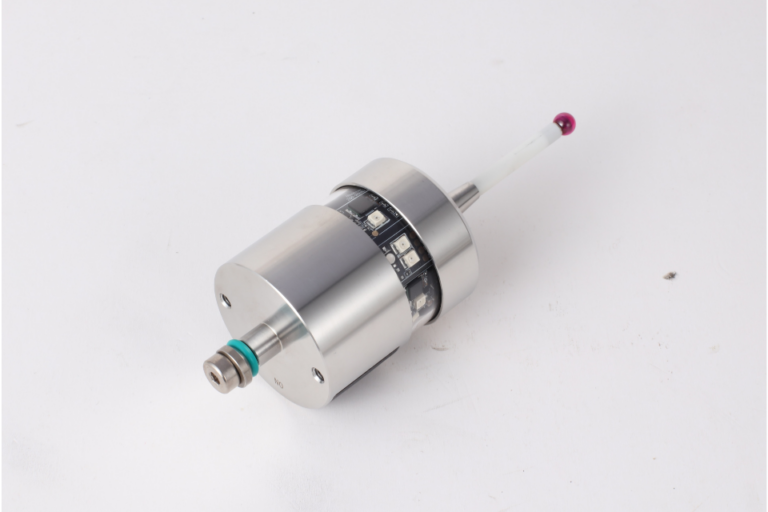
Explorar las herramientas láser CNC sonda cnc.
A continuación se exponen las categorías típicas de problemas con sondas fallidas, con el contexto real del taller.
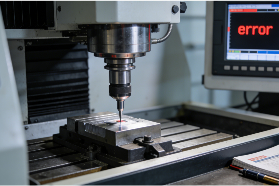
Cómo se siente en la máquina:
La máquina se acerca a la pieza...
No pasa nada...
Entonces aparece “Sonda fallida”.
Lo que suele ocurrir:
El controlador nunca vio la señal de disparo dentro del rango o tiempo esperado.
Principales causas y soluciones:
El verdadero cambio de mentalidad:
No dé por sentado que la sonda se dispara porque vea un contacto mecánico. El controlador debe ver la señal electrónicamente, y eso es lo que determina el éxito o el fracaso.
Más información sobre los palpadores modulares CNC sonda cnc.
Síntomas:
Errores de palpado que se producen sin siquiera entrar en contacto con la pieza.
Errores que se producen a mitad de recorrido o en el aire libre.
Probables culpables:
Arreglos que realmente ayudan:
Explorar los reglajes de herramientas CNC de un eje por cable sonda cnc.
Aunque la sonda se dispare, es posible que no se comporte como espera el controlador.
Los errores de configuración más comunes son:
Cómo diagnosticar:
Enfoque fijo:
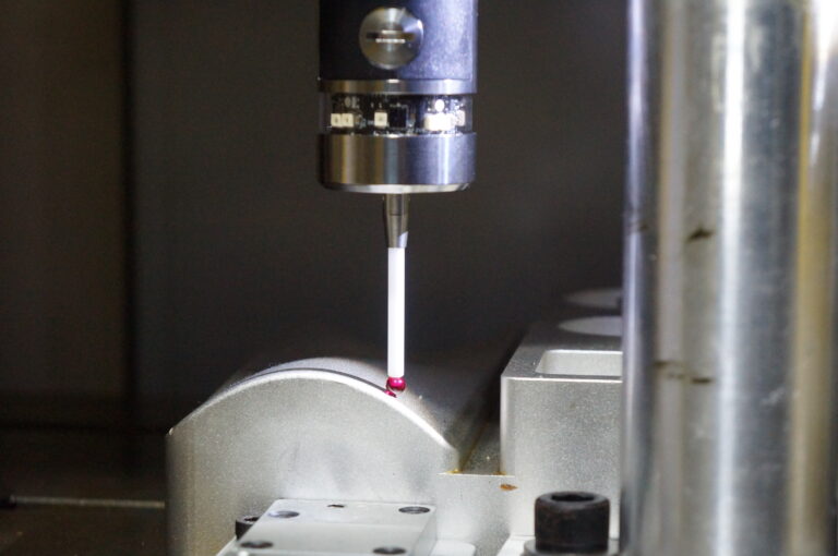
Sondas CNC de medición de alta precisión sonda cnc.
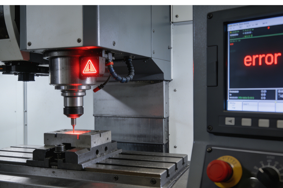
Un factor del que no se suele hablar lo suficiente es el ruido eléctrico en el armario o en la zona de herramientas.
Entre las fuentes figuran:
Arreglos que ayudan:
Explorar los palpadores con cable de transmisión CNC sonda cnc.
A veces, el hardware de la sonda está bien, pero el controlador no está configurado para ello.
Algunos ejemplos son:
Este tipo de error tiende a repetirse en cada intento de sondeo hasta que se soluciona, lo que en realidad es una bendición: significa que el problema es de configuración, no un fallo intermitente del hardware.
Visite la página de CNC Probe sonda cnc.
En lugar de conjeturas al azar, he aquí una secuencia lógica que se ajusta a la experiencia real de la tienda:
Si no es así, tiene un problema de conexión, alimentación o hardware de la sonda.
Supervise el diagnóstico del controlador mientras toca la sonda en lugares conocidos.
El cambio de la aguja, el restablecimiento de la calibración o el desvío del cableado son grandes desencadenantes de nuevos problemas.
Esto es sutil, pero a menudo es la raíz de “fallos aleatorios”, no de diagnósticos que se repiten de forma fiable.
Eche un vistazo a nuestro ajustador de herramientas CNC de eje Z cableado sonda cnc.
La razón por la que las alarmas de “sonda fallida” son tan confusas es que muchos maquinistas asumen que el contacto mecánico equivale al éxito. Pero lo que importa es la interpretación que hace el controlador de una señal eléctrica. Piense en el palpado como una canalización de datos:
Movimiento del palpador → señal eléctrica → lógica del controlador → interpretación de coordenadas.
Cualquier rotura o distorsión en esa tubería -física, eléctrica o de configuración- conduce a un ciclo fallido.
| Causa Categoría | Qué se siente | Solución práctica |
|---|---|---|
| No se ha visto ningún desencadenante | Se mueve pero falla | Comprobar baterías, cableado, armado, calibración |
| Gatillo falso | Error en el aire libre | Reducir el ruido, asegurar el palpador, añadir blindaje |
| Deriva de calibración | Errores de desplazamiento consistentes | Recalibrar, acortar palpador, verificar parámetros |
| Ruido ambiental | Comportamiento errático | Toma de tierra, desvío de cables, supresión de ruidos |
| Problema de configuración | Repite cada intento | Comprobar ajustes/macros del controlador |
Más información sobre los palpadores de infrarrojos CNC de alta calidad sonda cnc.
“El ”fallo de la sonda" no es una sentencia de muerte para su configuración de sondeo, sino una pista de diagnóstico. El truco está en comprender que la sonda no es solo un interruptor de contacto mecánico, sino que forma parte de un sistema de medición electrónico en el que la conexión a tierra, la integridad de la señal, la calibración y la configuración del controlador desempeñan un papel esencial.
Una vez que empiece a pensar en términos de interpretación de señales en lugar de sólo en sondas físicas, resolverá los problemas de “sonda fallida” de forma rápida y eficaz.