Fale connosco, obtenha uma solução em 20 minutos
Por favor, informe-nos sobre quaisquer requisitos e exigências específicas, para que possamos encontrar a solução o mais rapidamente possível e enviá-la de volta gratuitamente.
Por favor, informe-nos sobre quaisquer requisitos e exigências específicas, para que possamos encontrar a solução o mais rapidamente possível e enviá-la de volta gratuitamente.
Encontrar um 0,0,0 fiável no seu CNC - o ponto onde X, Y e Z se encontram - é um dos primeiros passos reais para uma maquinação precisa. Quer esteja a fazer peças únicas ou produções, acertar no zero significa que o seu programa irá atingir as caraterísticas onde deve. Tradicionalmente, os operadores utilizavam localizadores de arestas, indicadores ou um simples alinhamento visual. Mas com um apalpador e a abordagem correta - utilizando placas, pucks e rotinas de apalpação - obtém sempre precisão, repetibilidade e confiança.
Não se trata de memorizar uma macro - trata-se de compreender porque é que utilizamos ferramentas e sequências específicas e como pensar como alguém que confia na sua máquina em vez de adivinhar.
Em termos mais simples, a colocação em zero consiste em estabelecer um ponto conhecido numa peça de trabalho - normalmente o canto, centro ou superfície que o resto do programa irá referenciar. Esse ponto torna-se a base do seu sistema de coordenadas de trabalho (G54, G55, etc.). Se esse ponto estiver mesmo com alguns milésimos de desvio, todos os movimentos posteriores agravam esse erro. Com uma sonda, a colocação em zero não é um trabalho de adivinhação, é um dado medido.
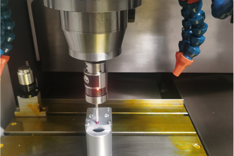
Saiba mais sobre os configuradores de ferramentas laser CNC sonda cnc.
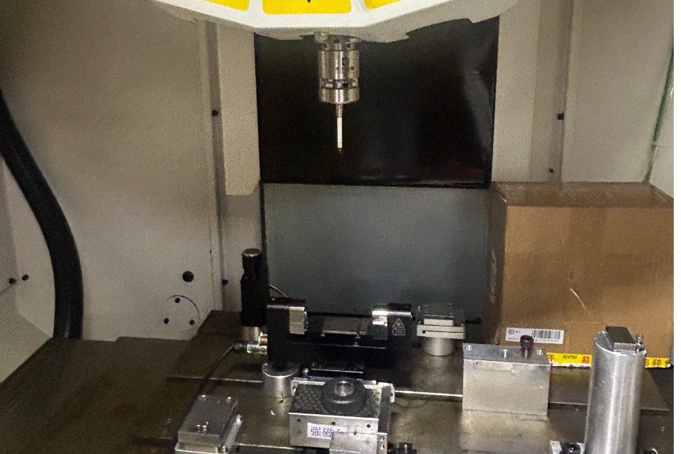
Uma placa de sonda é uma placa metálica de precisão colocada na mesa da máquina ou na sua peça de trabalho. Esta placa fornece uma superfície previsível e conhecida que é utilizada para encontrar o zero Z (definindo a altura de trabalho). Uma vez que a espessura da placa é conhecida e consistente, quando a sonda entra em contacto, o controlador pode calcular automaticamente a verdadeira localização da superfície utilizando o valor da espessura da placa introduzido na sua rotina de sondagem.
Esta é uma abordagem amplamente adoptada porque:
Na prática, executa-se um ciclo de apalpação que baixa a ferramenta até ao contacto com a placa, regista o ponto de contacto e, em seguida, desvia Z zero com base na espessura conhecida da placa.
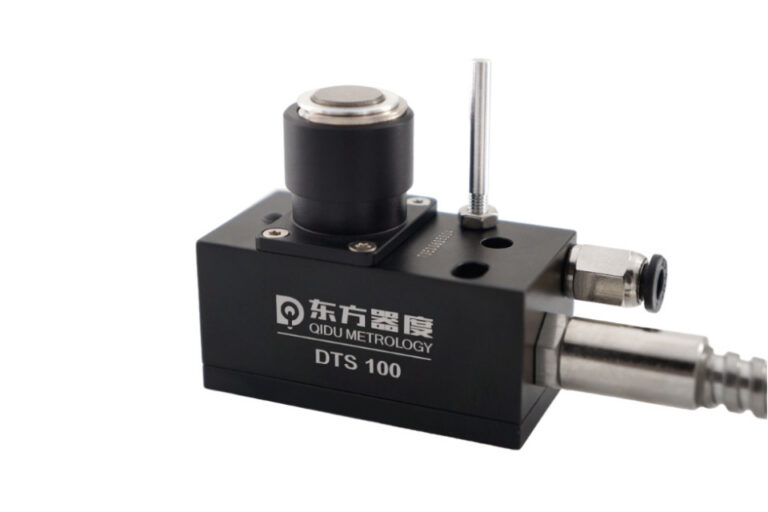
Explorar os apalpadores tácteis modulares CNC sonda cnc.
Um disco de sondagem é um bloco sólido - frequentemente magnético ou fixado no local - utilizado para referenciar as posições X e Y. É particularmente útil para:
Porquê discos? Pense da seguinte forma: se o objetivo é encontrar o zero X e Y, está essencialmente a perguntar “onde está este ponto conhecido em relação ao mundo da minha máquina?” Com um disco, pode aproximar-se dele a partir de diferentes eixos, sondar a sua superfície e utilizar essas posições medidas para determinar matematicamente o verdadeiro zero X/Y.
Esta abordagem elimina grande parte da interpretação manual que os localizadores de arestas requerem (sabe, onde se arrasta lentamente até o mostrador se mover), permitindo que a máquina sinta e registe pontos exactos.
Verificar os apalpadores com fio para transmissão CNC sonda cnc.
Para muitos sistemas de sondagem - quer esteja a utilizar um controlador dedicado ou macros práticas - estas rotinas seguem uma sequência que reflecte um padrão de pensamento comum no chão de fábrica:
Colocar a placa no dispositivo de fixação ou no material e fixá-la para que não se desloque. Certifique-se de que o disco ou a placa estão limpos e que a ligação à entrada da sonda é sólida.
É como afinar o instrumento antes de tocar - se a referência for instável, tudo o que se segue não será fiável.
A sequência típica de apalpação em muitos controladores (especialmente software de macro-driven ou CNC com suporte de apalpação) começa por descer até que a sonda contacte a placa ou a superfície da peça.
Estabelece-se assim uma altura de referência.
Normalmente, tem o seguinte aspeto:
A ideia aqui é simples: definir primeiro onde está o topo da peça de trabalho. Sem isso, não é possível definir com confiança as origens X/Y porque Z está a flutuar na incerteza.
Quando Z é conhecido, os passos seguintes são sobre X e Y:
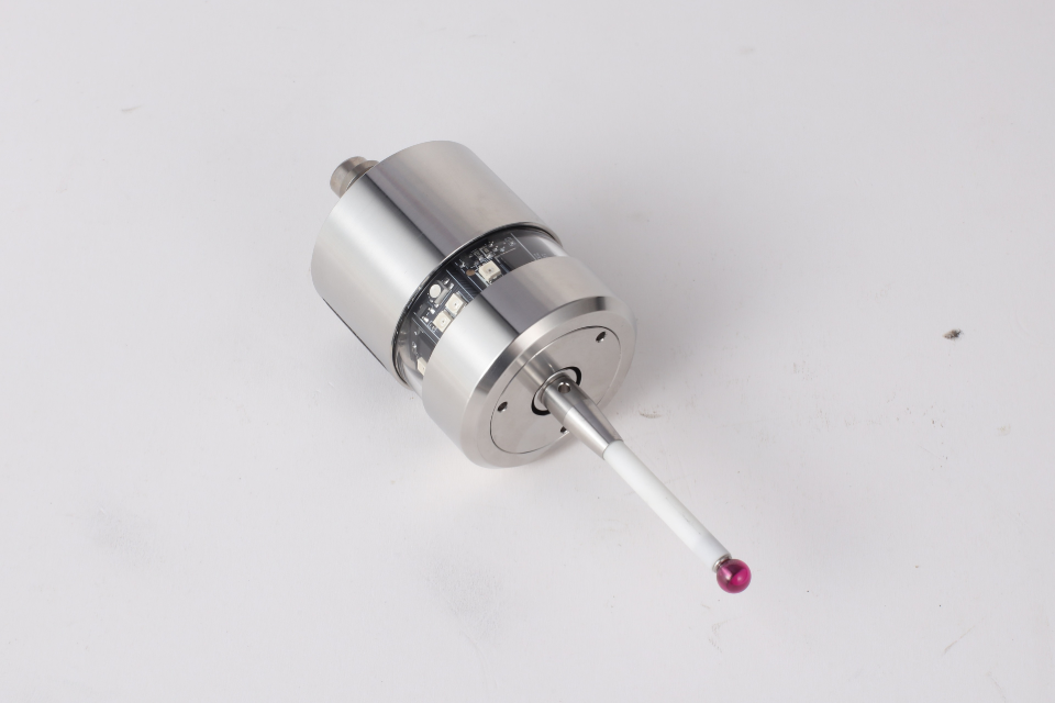
Esta sequência minimiza os erros devidos à deflexão da haste de apalpação, ao pré-curso do apalpador e à excentricidade do fuso. Por outras palavras, ao medir duas faces opostas e calcular a média, está a deixar que a medição da máquina dite o zero, e não a sensação humana.
Saiba mais sobre os ajustadores de ferramentas com fio do eixo Z do CNC sonda cnc.
Pode perguntar-se: “Porque é que não se limita a encontrar a borda ou a olhar para ela?”
Aqui está a verdade mais profunda: os métodos manuais dependem da habilidade e variabilidade do operador. Dois maquinistas podem encontrar a mesma peça e obter pequenas diferenças. Uma sonda, com placas e pucks, reduz a interpretação humana e permite que os codificadores da máquina o informem das coordenadas exactas.
No fabrico moderno, procuramos confiança e repetibilidade - dados reproduzíveis que qualquer operador possa executar e confiar.
Visite a página inicial do CNC Probe sonda cnc.
Uma questão que surge frequentemente na prática é: “Tenho de sondar novamente após uma passagem de corte diferente?”
A resposta nem sempre é sim - mas muitas vezes é sensata:
A ideia mais profunda aqui é: a sondagem não é um processo único. Está essencialmente a validar as suas referências ao longo do processo. Quando perder a confiança no seu ponto de referência (mudança de ferramenta, mudança de fixação, vibração), volte a sondar.
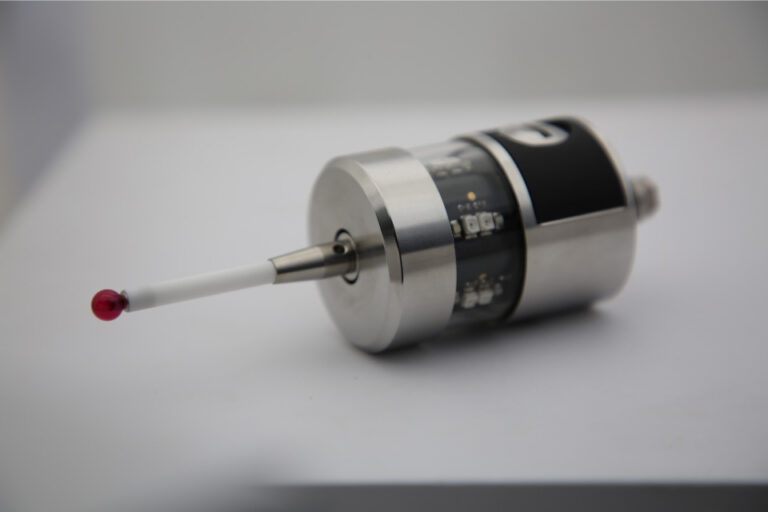
Explorar sondas CNC de medição de alta precisão sonda cnc.
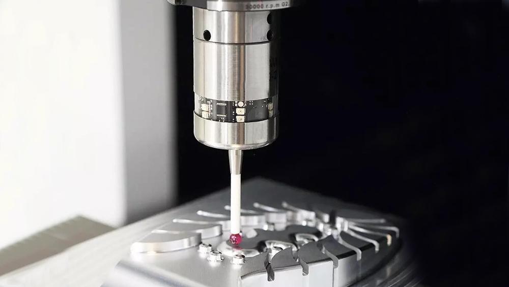
Saiba mais sobre as ferramentas de ajuste tátil CNC com fio ótico de cinco eixos sonda cnc.
Os operadores experientes pensam em termos de superfícies e geometria de referência - e não apenas em movimentos de código G. O que está realmente a fazer com a sondagem é responder a estas perguntas:
Quando se enquadra o zeramento desta forma, a utilização de placas, discos e rotinas começa a fazer sentido de forma intuitiva.
Zerar com uma sonda não é um truque de magia. É uma estratégia de medição baseada em pontos de contacto previsíveis e coordenadas consistentes:
A máquina torna-se um dispositivo de metrologia e não apenas uma máquina de corte. Esta é a diferença entre esperar que a sua configuração seja boa e saber que o é.