Talk to us,Get a Solution in 20 minutes
Please let us know any requirements and specific demands,then we work out the solution soonest and send back it for free.
Please let us know any requirements and specific demands,then we work out the solution soonest and send back it for free.
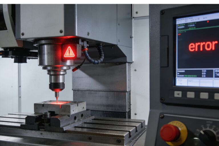
There’s a moment in every CNC job where the part is clamped, the tool is loaded, the program is ready… and you pause because you know the truth:
If your XYZ zero is wrong, everything after it is just expensive artwork.
Probing makes zeroing faster, more repeatable, and way less “feel-based.” But it also introduces new ways to be wrong—subtle ones—like plate thickness assumptions, stylus deflection, bad approach directions, or the classic: “I probed Z, but forgot the tool length system I’m actually in.” CNC Probe
This guide is about doing XYZ zeroing like you mean it: using plates and pucks intelligently, building routines you trust, and avoiding the little traps that separate “it runs” from “it’s right.”
A probe doesn’t magically set your origin. It gives you a measured coordinate in machine space (or whatever coordinate system your control is reporting at that moment). Your job is to convert that into a meaningful work coordinate—usually a work offset like G54 (or a workpiece origin in your controller’s probing cycle).
So every probing workflow is basically:
Touch something known (surface/edge/pocket/feature)
Record where that touch happened
Apply a correction (probe tip radius, plate thickness, puck diameter, etc.)
Write the resulting value into your work coordinate system
If you keep that model in your head, troubleshooting becomes much easier.
Best for: Setting Z height fast and repeatably
Common setups:
Plate on top of the workpiece to set Z0 at the top face
Plate on the table to set Z0 at the table surface
Plate on a fixture to establish a consistent Z reference
What makes touch plates great:
Simple: just Z movement
Fast: one axis, minimal risk
Reliable: if thickness is known and consistent
What makes them dangerous:
Plate thickness wrong (or assumed) CNC Z-axis Wired Tool Setter (One-key Zeroing)
Chips under plate = fake Z
Conductive/contact issues if you rely on electrical touch
Wrong “Z0 definition” (top of stock vs finished surface vs fixture datum)
Best for: Setting XY (and sometimes Z) from a repeatable, known geometry
Why they’re powerful:
A puck gives you a consistent diameter/center reference. That’s a big deal because real parts lie, castings are ugly, stock isn’t always square, and vise jaws aren’t always perfectly parallel.
Typical use cases:
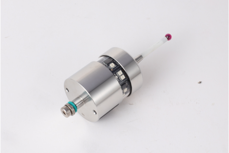
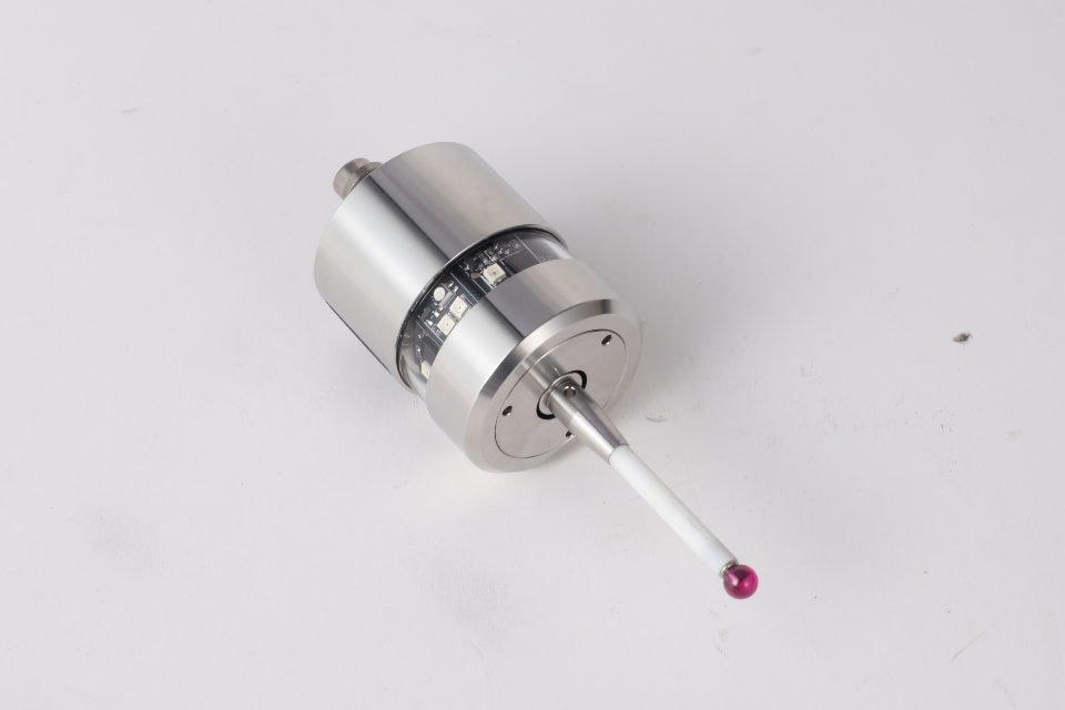
Find XY by probing around a puck and calculating the center High-Precision Wireless Radio Touch Probe
Use a puck in a fixture as the “fixture coordinate anchor”
Use a known bore/ring gauge to set a consistent work origin across jobs
Watch-outs:
Puck not seated flat (chips again)
Puck diameter not actually what you think (cheap pucks vary)
Probe tip radius compensation not applied correctly
Probing speed too high → stylus flex → “repeatable wrong”
Before routines, build your trust chain:
Probe health check
Does it trigger consistently?
Is the stylus tight?
Any crash history lately? (Probes remember.)
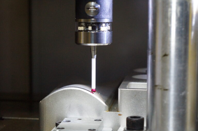
Calibrate your probe tip radius (and ideally, stylus offsets)
Calibrate your probe tip radius (and ideally, stylus offsets) CNC Modular Touch Probe
If not, you can calibrate against a known ring gauge and measure repeatability.
Decide what coordinate system you’re setting
Work offset (G54/G55…), or controller-specific workpiece coordinate, or a probing macro that writes directly to offsets.
Define your datum like a drawing does
A good datum definition is not “somewhere near the corner.” It’s: X0/Y0 is the intersection of these two faces. Z0 is this top surface (or finished surface after facing). Origin is on part, fixture, or stock—on purpose when those are clear, plates and pucks become tools—not guesses.
Clean the surface
Wipe the top of the part and the plate bottom. Chips are not “small.” Chips are “offset generators.”
Place plate consistently
Put it where it won’t rock, preferably on a flat region away from burrs.
Approach in two stages
Fast approach to safe height
Slow final approach for trigger
This reduces cycle time without sacrificing accuracy.
Apply plate thickness properly
If you touch the plate top, your actual Z reference is plate thickness below that (if you’re setting to the work surface). Your routine must add/subtract correctly.
Write to the correct place
If you’re using tool length offsets: make sure you’re setting work Z, not hacking tool length (unless that’s your chosen method).
If you’re in a router-style workflow (like many hobby/prosumer controls), make sure you’re not mixing “machine Z” and “work Z.”
Workflow 1: “Z0 is top of stock”
Probe plate on top of stock
Z0 becomes the stock top
Great for surfacing, pocket depths, engraving
Workflow 2: “Z0 is table/fixture plane”
Probe plate on table or fixture datum surface
Z0 is consistent across setups
Great for repeatable fixturing and parts you remove/reinstall
Both are valid. Mixing them mid-job is where chaos starts.
Best when: Your stock is square-ish and edges are real datums
How it works:
Probe X face → find X edge location
Probe Y face → find Y edge location
Apply probe tip radius compensation
Set X0/Y0 at corner intersection (or offset as needed)
Pro tip:
Probe each edge twice—once from each direction—if you need high confidence. It reveals if you’ve got stylus flex or inconsistent triggering.
Best when: Your design has a reference hole/bore
You probe multiple points around the bore and calculate the center.
Why it’s elite:
A bore center is less sensitive to stock shape, vise clamping, or slightly ugly exterior surfaces. It’s a design-intent datum more often than a raw edge.
Best when: You do repeat jobs or use fixtures
Put a puck in a known spot on the fixture plate (or a precision dowel + probing routine), and always set XY from that.
This is how pros stop “indicating every time.”
You’re building a coordinate system that lives with the fixture, not the mood of your setup.
If you want one workflow that covers most real jobs:
Set Z0 on top of stock using a plate (fast, safe).
Set XY0 by probing two edges (if edges are datums), or
set XY0 from a bore/puck (if precision and repeatability matter).
Confirm with a sanity check move. Jog to a known point (like the corner you expect) at safe Z .Visually verify you’re not living in a parallel universe, run a dry-run / air-cut at safe Z for the first operation.
This is not “extra steps.” This is “cheap insurance.”
A probe triggers on contact, but the machine still has inertia, and the stylus can flex.
Practical rules:
Final approach feed should be slow (especially on small probes, long styli, or springy setups). Use onsistent approach direction for repeatability.Don’t probe dirty surfaces (chips, coolant film blobs, burrs) Don’t probe soft or gummy materials aggressively (it can smear or “catch”).Temperature matters more than people admit—especially with long cycles or warm spindles.If you want “deep mind” accuracy: treat probing like metrology, not jogging.
Symptom: Everything is consistently off in Z by a fixed amount
Fix: Measure plate thickness with a mic, write it on the plate, use that value.
Symptom: Probing “works,” but the program cuts in the wrong place
Fix: Confirm what your probing routine updates (G54? active WCS? tool offset?).
Symptom: XY is off by roughly the probe ball radius
Fix: Make sure routines subtract/add stylus radius correctly for edge probing.
Symptom: Repeatability is “consistent-ish” but not tight
Fix: Slow final approach feed, shorten stylus if possible, reduce overtravel.
Symptom: Offsets shift after deburring or after first op
Fix: Deburr the datum faces before probing, or probe internal features instead.
A good probing routine has these traits:
Safe approach and retract moves (no surprise Z dives)
Two-stage feed (fast approach, slow touch)
Repeat touch logic (optional but powerful)
Clear output (it should tell you what it set: X/Y/Z and which offset)
A fail-safe (if no trigger occurs within expected travel, stop)
If your controller supports macros or canned probing cycles, your best upgrade is not “more probing”—it’s more structure: consistent probing templates you run the same way every time.
If you want to know whether your workflow is solid, do this: Probe XY from an edge or puck.move away. Probe the same feature again compare results.If you can repeat within your tolerance goals (and your machine capability), you’re good.If not, don’t blame the probe first—blame: dirty surfaces, speed, stylus length, loose mounting, or inconsistent approach direction. Probing is brutally honest.
Yes, probing is faster than edge finders and paper slips.
But the real upgrade is psychological:
You stop “hoping” your origin is right. You start knowing.
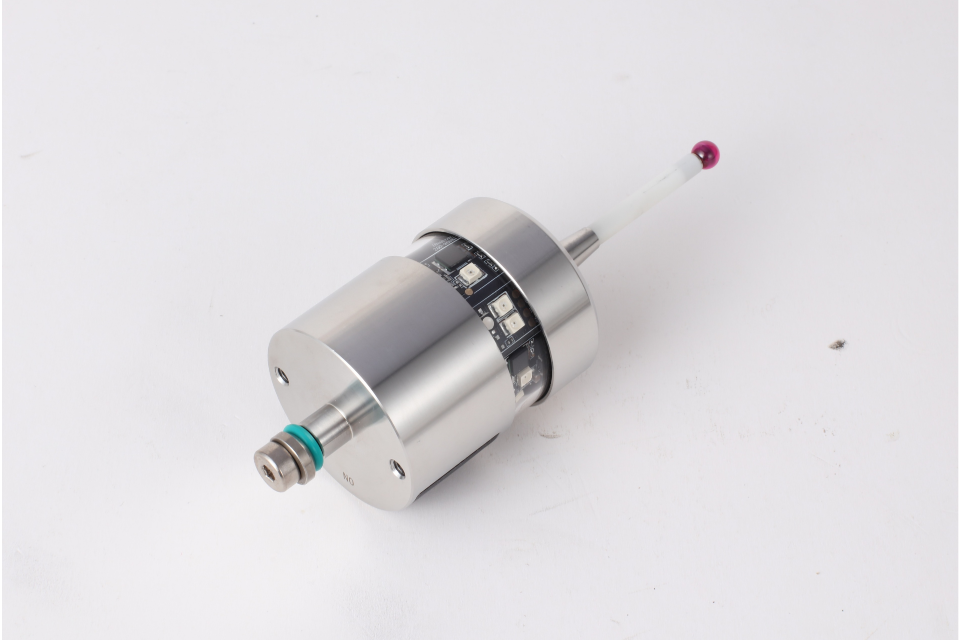
Plates make Z simple and safe. Pucks make XY repeatable and fixture-driven. Good routines make the whole process boring—in the best possible way. High-Quality CNC Infrared Touch Probe
And in CNC, boring is a feature.