Talk to us,Get a Solution in 20 minutes
Please let us know any requirements and specific demands,then we work out the solution soonest and send back it for free.
Please let us know any requirements and specific demands,then we work out the solution soonest and send back it for free.
If you’ve ever measured a bore, a sphere, or a nice smooth radius and thought:
“Why does this ‘perfect’ curve look slightly… three-lobed?”
You’re not imagining things. That pattern often comes from lobing error—a direction-dependent trigger behavior common in kinematic (mechanical-switch) touch-trigger probes. In plain terms: the probe doesn’t trigger at the exact same deflection in every direction, so the measured surface can come out with a subtle “triangular / three-lobe” signature.
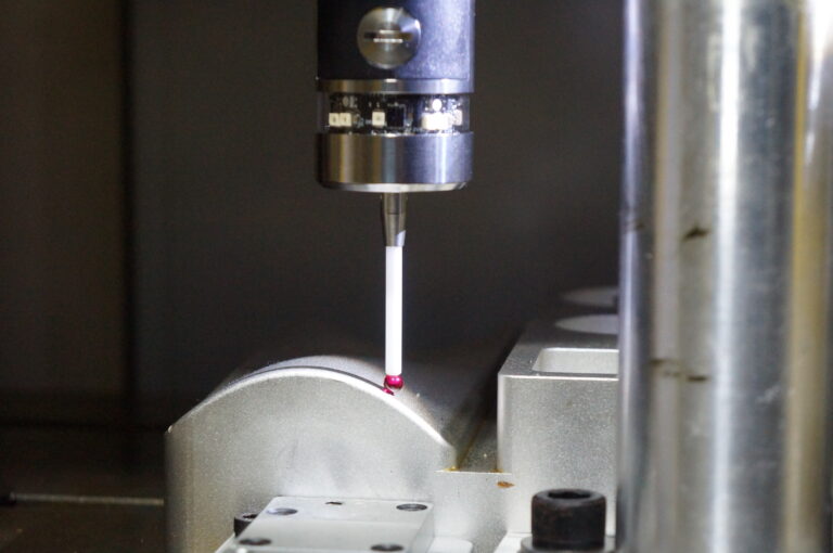
This blog is about reducing lobing specifically on curved features (bores, cylinders, spheres, fillets, large radii)—where the combination of surface normal changes + probe trigger direction changes makes lobing show up loud and clear.
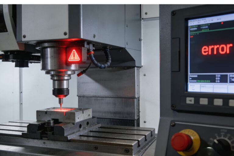
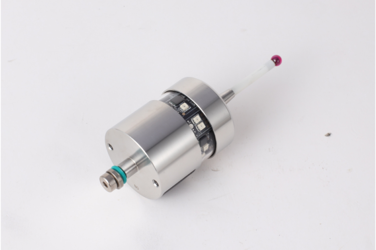
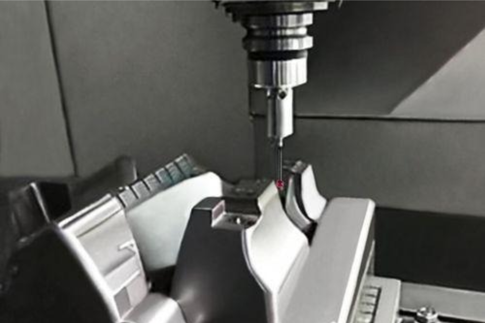
Kinematic touch-trigger probes use a mechanical switching mechanism. The trigger force required can vary with probing direction, creating small form errors commonly called “lobing.”
On a flat plane, you can often approach with a single consistent vector and get away with it.
On a curved feature:
And because pre-travel is affected by trigger direction, trigger speed, and stylus length/slenderness, your curve becomes a perfect canvas for lobing to paint on.
Here’s the mindset shift that beats competitors’ generic advice:
Lobing is often a stable, direction-dependent signature.
That means you can either:
Most shops do neither—they just “take more points” and hope.
More points can actually make a lobing pattern look more believable.
Before you “fix lobing,” do a quick sanity check:
If it’s not repeatable, suspect:
Higher trigger speed can increase pre-travel, and pre-travel varies with direction—exactly what lobing feeds on.
Shop rule:
For critical curved features, use a slower, consistent touch speed than your general inspection speed.
Longer or slender styli increase pre-travel and stylus deflection effects.
Practical moves:
Renishaw explicitly describes that “standard probes” using a mechanical switch can show lobing, and that strain-sensing probes (e.g., TP200) are designed to overcome that direction-variation issue. https://cnc-probe.com/cnc-touch-probes/
You don’t have to replace everything—but if your business lives on tight form of bores/spheres, this is one of the few changes that can reduce lobing at the source.
If you always approach a surface with the same probe orientation, you reduce how much the probe’s directional behavior changes between points—meaning less “lobed” form in the fit. This is common real-world practice among CMM/CNC probing users. https://cnc-probe.com/cnc-touch-probes/
How to apply this on curves:
Rotating the head to keep probing direction favorable can help, but only if your qualification matches the way you measure.
ISO-style probing performance tests explicitly involve probing in multiple orientations on a sphere (because direction matters).
Translation for the shop floor:
If you measure a bore with 3–5 different head angles, qualify those angles properly and verify with a sphere test program that resembles your measurement pattern.
Taking many points evenly around a bore can actually reconstruct the lobing shape beautifully.
Instead:
Your metrology software needs accurate probe tip calibration/qualification to know tip location and diameter before measurement.
But “qualified” doesn’t mean “lobing-proof.”
There’s established research on touch-trigger probe error compensation using generalized probe error models and even neural-network approaches—reporting significant error reduction in some cases.
In the real world, you can do a simplified version:
This is more effort than slowing down and shortening the stylus—but it’s how you win when you’re chasing form in the single-digit microns.
When a curved feature form matters (bores, spheres, radii):
It’s possible to change:
…without actually improving truth.
That’s why ISO-style thinking treats probing performance as intertwined with the CMM system and relies on test artifacts like spheres and multi-orientation probing for verification.
In practice:
Any lobing “fix” should be confirmed by a repeatable artifact test and a before/after comparison.