Talk to us,Get a Solution in 20 minutes
Please let us know any requirements and specific demands,then we work out the solution soonest and send back it for free.
Please let us know any requirements and specific demands,then we work out the solution soonest and send back it for free.
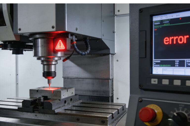
There’s nothing more frustrating than starting a probing cycle and boom — right away you get “Probe already triggered,” “always triggered,” or the machine behaves like the probe is already touching something when nothing is there.
This symptom can come from all kinds of root causes: electrical noise, wiring, logic state confusion, controller timing, and even how the controller interprets the probe state once it resets. But before we chase ghosts, the key is to understand what “always triggered” actually means and then zero in the true cause with a systematic troubleshooting mindset.
Let’s walk through this in a way that makes sense on the shop floor — no vague guessing, no wasted cycles — just clear diagnosis and fixes.
When a controller reports “probe always triggered” or behaves as if the probe is already closed before movement begins, it means the controller input thinks the probe signal is active even though you expect it not to be. That can show up as:
This is fundamentally a signal state problem — the control thinks the probe circuit is closed when it should be open (idle).
This warning is widely reported in CNC probing https://cnc-probe.com/cnc-modular-touch-probe-precision-measuring-stable-signal/contexts when the control believes the probe line is already active at the start of a probe move.
Troubleshooting works best when you group causes like this:
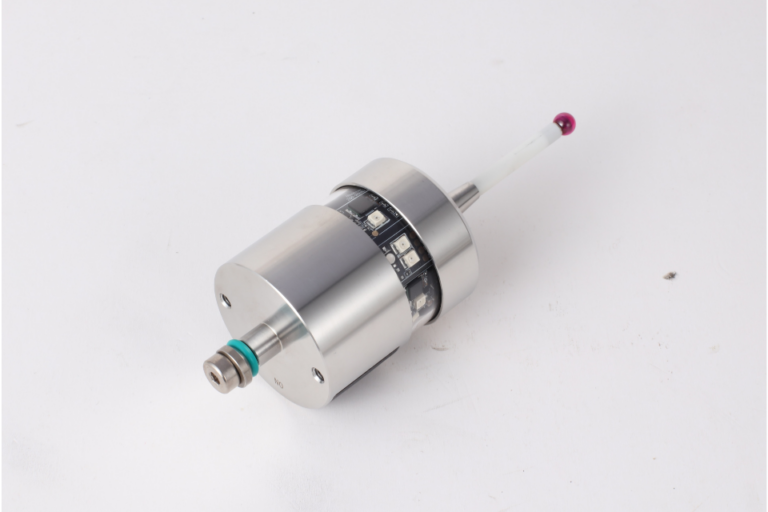
Many systems treat active as LOW and inactive as HIGH, or vice versa. If your probehttps://cnc-probe.com/cnc-touch-probes/ wiring is inverted compared to what the controller expects, the control will always read triggered.
→ This is common in hobby CNC controller configs (e.g., GRBL, FluidNC) where pins need to be set correctly for the probe type.
If the signal line isn’t biased properly, it can float and be intermittently seen as “triggered.”
This often happens if the controller input isn’t using a defined pull‑up or pull‑down, or the wiring is too long / unshielded — giving it extra false voltage.
Some CNC controllers or planner code paths don’t reset the probe state between cycles. As seen in some homing/touchplate threads, the probe triggers once then stays “active” logically until a power cycle.
Spindle mains wiring or other electrical noise can redirect signal paths, making the probe line appear active.
Some firmwares show an endstop “triggered” because the UI repurposes that diagnostic for probes — the hardware might be functioning, but the UI blinks the wrong status.
Long-term ESD events can slowly weaken input protection diodes and lead to lingering false signals.
If the controller doesn’t wait long enough after a trigger before sampling the idle state, it may think the probe is still active — which is exactly why many probing routines add a small delay after the trigger release before starting the next move.
Here’s how to structurally rule causes in/out:
Before changing wiring, find out:
If you can show the UI or status line changes without movement, your wiring/logic is likely okay — and the issue is higher‑level.
A floating or wrongly biased input will always look triggered:
Even a perfectly biased line will read active if there’s:
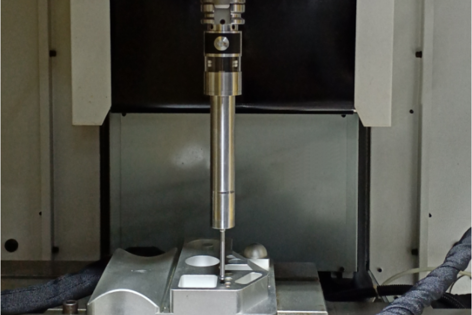
Take continuity readings with a multimeter to confirm the probe line only closes when intended.
Many systems like GRBL or FluidNC require explicit configuration of whether the probe is active LOW or active HIGH. If that doesn’t match the actual hardware, the control starts in the “triggered” state.
Sometimes the hardware is fine but the controller reads the state too early after activation. A short delay (e.g., 50–200–300 ms) after a trigger or before starting a new cycle can allow the controller to “see” the idle state cleanly. This is exactly why some controller implementations include post‑trigger delays.
If the symptom appears more when the spindle is powered or the drive is running, noise might be taking your signal line on a joyride. Try:
If everything hardware side is clean but it still reports wrong state:
| Symptom | Likely Cause | Quick Fix |
|---|---|---|
| Always “triggered” at start | Wrong logic/inversion | Reverse input polarity or reconfigure logic |
| Works once then stays triggered | Controller state not resetting | Power cycle or add debounce reset delay |
| Trigger false when spindle on | Electrical interference | Reroute cable, shielding, ferrite choke |
| Trigger never changes state | Faulty wiring or hardware | Continuity test and replace connectors |
| Trigger status flickers | Noise or floating input | Add pull‑up/down and tighten wiring |
The biggest trap in these errors is assuming the probe itself is bad. In most “always triggered” cases, the probe hardware is fine 80% of the time — what fails is the interpretation of the signal by the control.
So ask yourself:
Once you separate signal integrity from interpretation logic, the problem becomes solvable rather than mysterious.
If after running this entire workflow you still see persistent bad states, contact your probe or controller vendor. Many probing systems (especially touch‑trigger probes) have specific trigger timing and debounce behavior that must be respected by the controller firmware — and the vendor can tell you the exact expected wiring and logic behavior for your system.