Talk to us,Get a Solution in 20 minutes
Please let us know any requirements and specific demands,then we work out the solution soonest and send back it for free.
Please let us know any requirements and specific demands,then we work out the solution soonest and send back it for free.
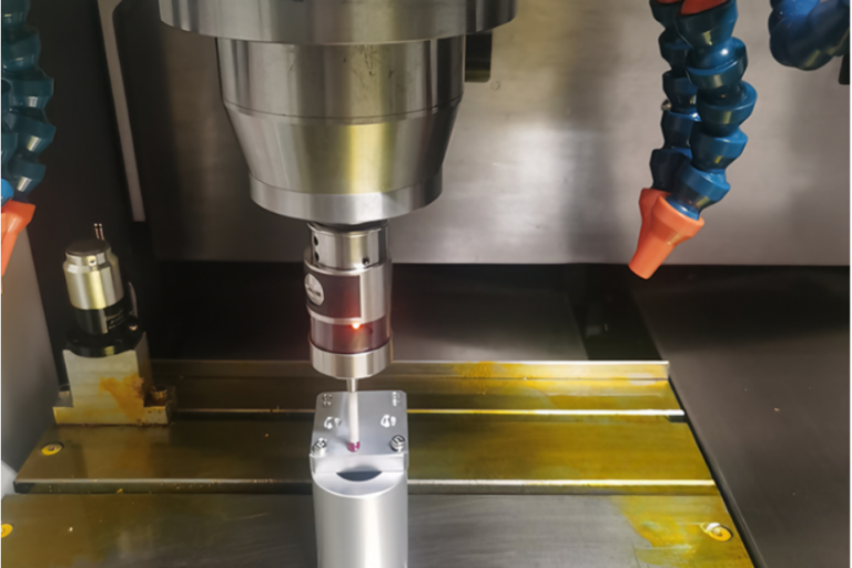
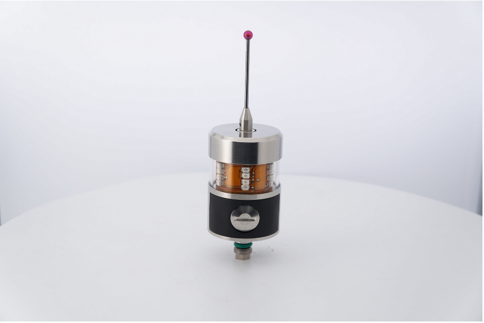
If you’ve ever watched a CNC machine “tap” a part a few times before machining—or pause mid-cycle to check a bore—you’ve seen probing in action. A touch probe (often called a workpiece probe) is a high-precision sensor mounted in the spindle (or turret) that touches the workpiece with a stylus ball to capture real 3D coordinates inside the machine, then feeds that data back to the CNC so it can set work offsets, align the part, compensate drift, or verify dimensions in-cycle.
Unlike “touching off” manually with paper or an edge finder, a touch probe turns that same idea into a repeatable, automated measurement loop.
A probe is essentially your machine’s “sense of touch.”
It can:
Find where the part really is (even if the fixture is a hair off)
Set the part zero (G54/G55… offsets) automatically
Measure features (bosses, bores, edges, pockets, angles)
Detect orientation/rotation (critical for castings, forgings, 5-axis setups)
Confirm finished dimensions before you unclamp—so you don’t discover a miss at inspection
That’s why probe makers describe touch probes as tools that record dimensions, form, and position characteristics by tactile contact with a stylus ball.
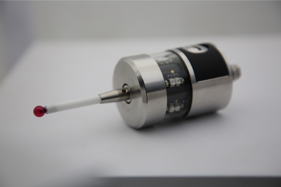
The stylus (usually a ruby ball) https://cnc-probe.com/cnc-probes-stylus/contacts the surface. The probe detects deflection and triggers a signal. The CNC records the machine position at that instant—boom: you have a measured point.
That trigger has to get to the controller reliably. In real shops, this is where the differences between probe systems matter a lot.
A common breakdown of probe communication methods includes: optical (infrared), radio, inductive, and direct/hard-wired transmission.
The probing cycle (macro/software) calculates:
centerlines,
distances/diameters,
angles,
offsets and compensation values,
…then updates offsets or stops the cycle if something is out of tolerance.
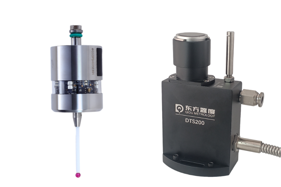
A touch probe measures the part (location, features, inspection points).https://cnc-probe.com/cnc-touch-probes/
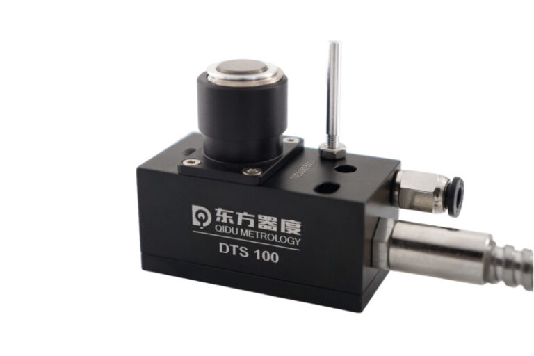
A tool setter / tool length measurement system measures the tool (length, diameter, breakage).https://cnc-probe.com/cnc-tool-setter/
They’re complementary. Many shops get the biggest payoff when they use both: tool measurement to stabilize cutters, and workpiece probing to stabilize setup/part position.
These are the workhorse probes most machinists first encounter. They trigger when the stylus deflects.
Renishaw is widely credited with inventing the touch-trigger probe in 1973, and machine tool users have benefitted from probing since the mid-1970s.
Some probe families generate the trigger signal using optoelectronic switching (e.g., shading a light barrier). This approach is described as wear-free and is used to support higher speeds and long-term stability.
Why it matters: less wear-driven drift and often better repeatability over time, especially in high-cycle production environments.
Some probes are designed to behave more uniformly in different approach directions (important for measuring circles and angles without “direction bias”). Probe makers explicitly distinguish multidirectional and bidirectional mechanisms, and discuss how design affects direction-dependent results and high-speed probing.
What to take away: if you’re probing in multiple directions (±X/±Y and Z), direction behavior can be the difference between “probing is magic” and “probing is… annoying.”
Find stock corner, set G54
Locate vise jaw reference
Align a part in soft jaws
Compensate when fixtures move after a crash or re-clamp
This is the “first win” most shops see: setup time drops, and the process is less dependent on one hero machinist.
Flipping parts between ops is a classic place where errors creep in. Probing makes re-establishing the coordinate system far more reliable than “indicate and pray.”
Probing isn’t only “before” and “after.” In-process probing enables:
checking a bore before finishing,
compensating tool wear (when used with proper cycles),
catching drift before it becomes scrap.
Probe suppliers explicitly position modern touch probes for in-process measurement and “continuous process chains,” including use under coolant.
“Necessary” depends on your mix, tolerance, and risk tolerance.
You only do simple 2D work,
tolerances are loose,
setups are identical for long runs,
and your scrap cost is low.
You run high-mix / low-volume jobs (job shops),
you do 5-axis or complex re-orientation,
you regularly hold tight tolerances,
you want lights-out or reduced supervision,
scrap or rework is expensive.
Touch probes are also a strong enabler for reduced staffing and automated process chains in modern machining environments.
Here’s a quick way to sanity-check value without spreadsheets.
Estimate:
Setup time saved per job (minutes)
Jobs per week
Machine hourly rate (or contribution margin rate)
Scrap/rework avoided per month
Example:
Save 12 minutes setup/job
25 jobs/week
Machine rate $90/hr
Time saved value/week:
12 min × 25 = 300 min = 5 hours/week
5 × $90 = $450/week
That’s $23,400/year in recovered spindle time before you even count scrap reduction.
Even if your real number is half, the payback can still be fast—especially if probing prevents a few high-value scrapped parts.
Use this like a pre-purchase spec sheet.
Flood coolant? Heavy chips?
Look for systems explicitly designed for reliable measurement under coolant conditions.
Spindle clearance constraints?
5-axis kinematics (need good direction behavior)?
From common probe system architectures:
Optical/IR: great for many machines, but needs line-of-sight discipline
Radio: good range and robustness; can be useful in larger machines
Inductive: for spindle-nose modules and tight integration
Hard-wired: often used in fixed tool-setting applications
Only find G54? (basic cycles)
Measure bores and compensate wear? (more advanced cycles + process knowledge)
In-cycle inspection reporting? (software integration)
Changing stylus length, ball size, or extension stack changes behavior. Calibrate each stylus configuration you actually run.
Avoid probing on heavy burrs
Probe clean surfaces when possible (air blast or coolant management)
Think about approach direction—especially on thin walls
The best probing routines are not “extra steps.” They’re insurance policies that are cheaper than scrap.
Myth 1: “A probe guarantees accuracy.”
Reality: It measures accurately when qualified, clean, and used correctly. Garbage surfaces and bad routines create garbage data.
Myth 2: “Probing slows the machine down.”
Reality: A few seconds of probing can save hours of rework and setup. Probe makers also emphasize reduced idle time when measurements are dependable at speed.
Myth 3: “Only big aerospace shops need probes.”
Reality: High-mix job shops often benefit the most because probing removes setup variability and reduces dependence on tribal knowledge.
Warm up / stabilize (if you chase microns, temperature matters)
Probe the fixture reference (optional but powerful)
Probe the stock/part datum → set work offset
Probe a key feature (like a bore) to confirm rotation/orientation
Machine
Probe critical dimensions (in-process or end-of-cycle)
Pass/fail decision: adjust offsets, re-cut finish pass, or stop the machine
This is the foundation for “confidence machining”—especially when you’re trying to scale quality.
A touch probe is not just a gadget that “touches the part.” It’s a feedback system: measure → decide → correct—right where errors are cheapest to catch: inside the machine, before you make scrap.