Talk to us,Get a Solution in 20 minutes
Please let us know any requirements and specific demands,then we work out the solution soonest and send back it for free.
Please let us know any requirements and specific demands,then we work out the solution soonest and send back it for free.
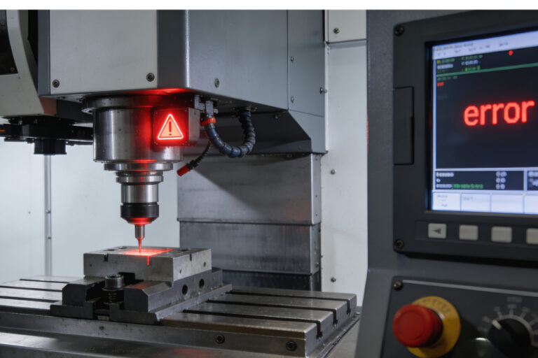
Touch probes are honest sensors living in a dishonest environment.
They’re trying to tell your control one simple truth—“I touched something”—while spindle drives, VFDs, servos, coolant pumps, and cable trays are doing their best impression of an RF transmitter.
So when probing gets flaky, people argue about the probe first. But in a lot of shops, the probe is fine—the signal conditioning isn’t.
This blog is a practical, shop-smart guide to three things that decide whether your probe input is rock solid or haunted:
Mechanical contacts don’t switch cleanly. They “chatter” for a short time when they change state. That’s why debouncing exists: many switches bounce for hundreds of microseconds, while logic inputs respond in nanoseconds, causing false triggers unless you filter it.
Touch probeshttps://cnc-probe.com/cnc-touch-probes/ and probe interfaces often include their own “re-arm” or debounce window for exactly this reason.
Noise is not bounce. Noise is the input line getting kicked by:
Noise creates fast spikes or ringing that can cross the logic threshold and look like “probe triggered”.
Why this matters:
You don’t fix noise with “more debounce” forever. Too much debounce can make probing sluggish or miss real events. You want the minimum filtering that makes the signal trustworthy.
A digital input needs a defined state when nothing is actively driving it.
A pull-up resistor gently biases the input to logic HIGH, so your input isn’t floating in the electrical wind.
This is so common that some controllers enable internal pull-ups by default. GRBL, for example, holds limit pins normally-high using the microcontroller’s internal pull-up resistors; a switch to ground pulls the pin low when triggered.
Many probe outputs are open-collector / open-drain or solid-state relay style—meaning they can pull the line one direction, but they don’t actively drive both high and low. You supply the bias.https://cnc-probe.com/cnc-transmission-wired-touch-probe-high-accuracy-signal/
You’re balancing two forces:
If you’re running long cables past noisy equipment, a weak pull-up is basically an antenna subscription.
Practical guidance:
Debounce should ignore the brief “chatter” around a state change, and only accept a stable state.
LinuxCNC’s debounce component describes a simple, robust approach: it increments a counter when the input is true and decrements when false, switching the output only when the counter hits thresholds. That design rejects brief spikes and bounce.
GRBL also documents two approaches for switch-like inputs:
If you crank debounce high enough, you can suppress noise—and also introduce:
That’s why many probe interfaces choose a controlled, modest lockout (e.g., MI 8-4’s 20 ms re-use delay) rather than “infinite smoothing.”
Healthy mindset:
Debounce is for mechanical truth.
Noise filtering is for electrical lies.
Noise filtering isn’t one thing. It’s layers:
A screened cable for probe status when driving a TTL input, and for longer runs (3–10 m) where interference may be encountered.
Practical habits:
If your controller input is “too sensitive” or sees ringing, a classic fix is an RC filter, sometimes followed by a Schmitt trigger (hysteresis) so slow/noisy edges become clean logic transitions.
Shop-friendly RC starting point (conceptual):
If you’re bringing a probe into a PLC/industrial DI module world, you get:
Industrial digital input standards like IEC 61131-2 define types of digital input characteristics; TI notes DI modules often use comparators with hysteresis and highlights IEC 61131-2 receiver types.
If your shop is electrically brutal (big VFDs, long cable runs, mixed grounds), this approach is often more reliable than “keep tweaking debounce”.
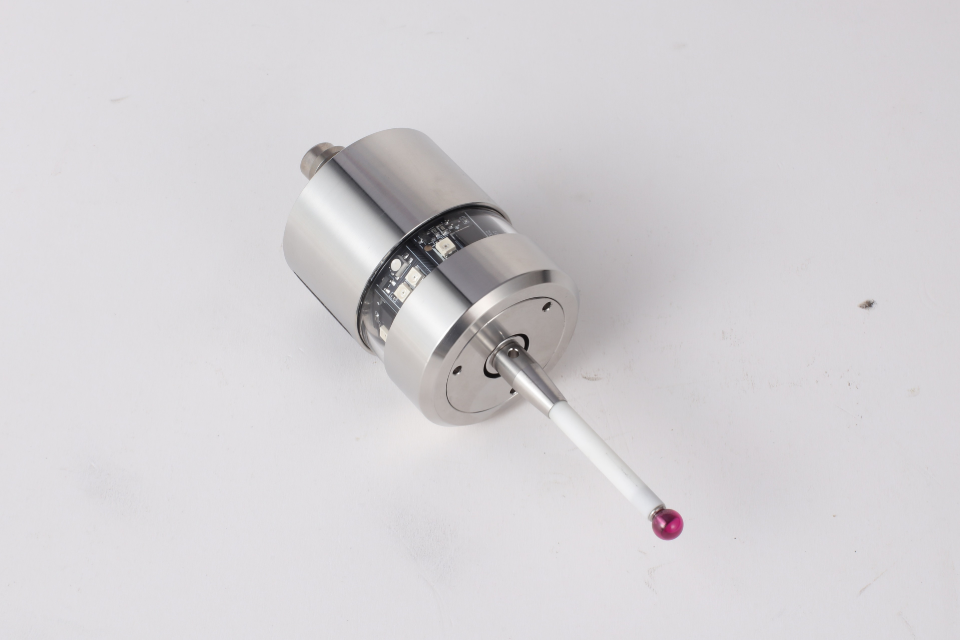
Probe systems commonly output things like:
Translation: your “probe input” might not be a clean logic line. Treat it as an industrial signal that needs conditioning.
For limit switches and safety-related inputs, many systems prefer normally-closed wiring so a broken wire looks like a fault.
GRBL documents how pin inversion interacts with normally-open vs normally-closed wiring logic.
For probing (not safety), you still want predictability. If the controller supports it, choose a mode where open wire = obvious error, not “random triggers”.
If you’re seeing random probe hits, false triggers, or inconsistent probing:
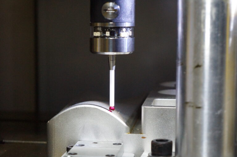
A touch probe isn’t just “a button that closes.”
It’s the front door to your coordinate system. If that door jitters, everything downstream—tool offsets, part alignment, in-process inspection—becomes politely wrong.
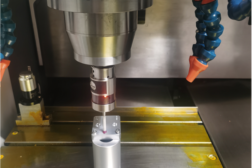
So the goal isn’t “no more false triggers.”
The goal is a probe signalhttps://cnc-probe.com/high-quality-cnc-infrared-touch-probe-with-wireless-link/ that is electrically boring: